K Sparky
Well-known member
GM Ignition Module and Ignition Coil Swap for 1986-1989 Suzuki Samurai 1.3 L Carbureted Engine Models.
Parts require:
1) GM Ignition Module (LX301 Ignition Control Module) Amazon $10 (Note a Delphi DS10071 Ignition Control Module has been shown to be a better choice for high rpm use ( ThankYou for the input Paul))
2) GM Ignition Coil (UC15T Ignition Coil) Amazon $11
3) Wire (Preferably a paired white green combo like an old computer power cord) Free
4) Two GM ignition module connectors or four spade connectors Amazon module connectors $10 each, Spade Kit $9
5) Heat Sink for GM HEI Ignition Module Amazon $15
6) Solder $10
7) Heat Shrink Wrap Tubing Amazon Tube Kit $10
8 ) Zip Ties or Wire Ties (Single strand copper or bailing wire work) Harbor Freight $5
9) RTV Autozone $6
10) Bolts for Heat Sink / Ignition Module Mounting Any Hardware Store $1
Total cost if you don?t have anything on the list to start with and don?t use a computer heat sink instead of the GM heat sink is about $88 bucks. If you have most the stuff like shrink wrap, RTV, bolts, solder, spade connectors, and the like and all you need is the GM Ignition module and coil it will run you less then $25. The best part is that you can carry a back up ignition module with you in the glove box for $11 and swap it out on the trail easily.
Tools required for the job:
A) 17 mm socket and ratchet for rotating engine to top dead center
B) 12 mm socket and ratchet for removing and installing distributor
C) Soldering Iron
D) Needle Nose Pliers
E) Phillips Head Screwdriver
F) Standard Screwdriver
G) Heat Gun
H) Cordless Drill, 11/64 bit, 5/64 Bit, and a Step Bit or Debur Tool
This ignition module swap is largely based off of the Toyota to GM module swap popular in the 20R and 22R powered Toyota pickup trucks. The biggest difference in this is Suzuki and Toyota systems are that Suzuki has placed the ignition control module under the distributor while Toyota used an externally mounted ignition module. This made the GM ignition module a more obvious choice for the Toyota application because the hall effects sensor that serves as ignition pickup coil is similar in the GMapplication and the wiring is fairly straightforward. However, the ignition pickup coil under the distributor cap on the Suzuki is also a hall effects sensor and will trigger the GM ignition control module just as well. Some people have tried just wiring in a GM module just like the Toyota setup and it has not worked because the wires coming out of the Suzuki distributor are made to connect to the coil and the no off signal it sends won?t trigger the GM module. So, it takes a little more work prepare the wiring for the Suzuki application to work. The following writeup is how I got the GM Ignition system to work on a 1988 Suzuki Samurai. The Suzuki and GM wiring diagrams are shown below. After that I show the hybrid GM/Suzuki ignition wiring diagram.

Suzuki Ignition Wiring Diagram


Procedure steps:
1) Remove positive battery terminal cable.
2) Rotate engine to top dead center cylinder one using 17 mm socket and ratchet.


3) Remove distributor cap and make sure the engine is at top dead center and the rotor is pointing to cylinder one firing position.


If the rotor is pointing to the #4 TDC location either rotate the crank 360 degrees or just make note that it was not at #1 work accordingly the important thing is getting the distributor and rotor back in with the same orientation it came out with.
4) Note the location of the rotor and distributor and mark them so they can be placed in the same orientation when the distributor is reinstalled. Once this is done remove the bolt holding the distributor in place and onto the engine using the 12 mm socket and ratchet. The bolt should be on the right side of distributor.


5) Now disconnect the wire connector from the wire harness and remove the distributor by pulling vertically and twisting back and forth until the distributor comes out.

If you look at the wires going out of this connector and those attached to the coils you should see agreement with the Suzuki wiring diagram.


6) Block off the distributor whole with the rag or shop towel to keep debris from getting into the engine block while the distributor is removed. Note it is also a good idea to put the 12mm bolt back in the hole so it does not get misplaced.

7) Once the distributor has been removed you can move indoors amd work on a bench or table as you will not need to be in the engine bay until the work on the distributor internals is complete.

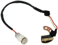
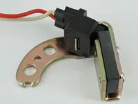
8 ) Remove the rotor for better access to the components below it. Use the standard screwdriver or needle nose pliers to remove the plastic cover on the internal ignition module. Then use the phillips head screwdriver remove the two screws holding the internal ignition module in place in the distributor.


9) Use the phillips head screwdriver to take out the screws holding the connectors from the ignition pickup coil to the internal ignition module. Now pull the ignition module andthe wire with the wiring harness connector on it free from the distributor.


10) Cut off the connector wire from the ignition module leaving about 6 inches of wire pigtailed out from the connector and set it aside. This will be used for power to the GM ignition module and will allow you to utilize the samurai wiring harness too make this a much more plug and play application since brown and black/white wire pairs are already connected into the wiring harness and power in the way we want to use them.

Parts require:
1) GM Ignition Module (LX301 Ignition Control Module) Amazon $10 (Note a Delphi DS10071 Ignition Control Module has been shown to be a better choice for high rpm use ( ThankYou for the input Paul))
2) GM Ignition Coil (UC15T Ignition Coil) Amazon $11
3) Wire (Preferably a paired white green combo like an old computer power cord) Free
4) Two GM ignition module connectors or four spade connectors Amazon module connectors $10 each, Spade Kit $9
5) Heat Sink for GM HEI Ignition Module Amazon $15
6) Solder $10
7) Heat Shrink Wrap Tubing Amazon Tube Kit $10
8 ) Zip Ties or Wire Ties (Single strand copper or bailing wire work) Harbor Freight $5
9) RTV Autozone $6
10) Bolts for Heat Sink / Ignition Module Mounting Any Hardware Store $1
Total cost if you don?t have anything on the list to start with and don?t use a computer heat sink instead of the GM heat sink is about $88 bucks. If you have most the stuff like shrink wrap, RTV, bolts, solder, spade connectors, and the like and all you need is the GM Ignition module and coil it will run you less then $25. The best part is that you can carry a back up ignition module with you in the glove box for $11 and swap it out on the trail easily.
Tools required for the job:
A) 17 mm socket and ratchet for rotating engine to top dead center
B) 12 mm socket and ratchet for removing and installing distributor
C) Soldering Iron
D) Needle Nose Pliers
E) Phillips Head Screwdriver
F) Standard Screwdriver
G) Heat Gun
H) Cordless Drill, 11/64 bit, 5/64 Bit, and a Step Bit or Debur Tool
This ignition module swap is largely based off of the Toyota to GM module swap popular in the 20R and 22R powered Toyota pickup trucks. The biggest difference in this is Suzuki and Toyota systems are that Suzuki has placed the ignition control module under the distributor while Toyota used an externally mounted ignition module. This made the GM ignition module a more obvious choice for the Toyota application because the hall effects sensor that serves as ignition pickup coil is similar in the GMapplication and the wiring is fairly straightforward. However, the ignition pickup coil under the distributor cap on the Suzuki is also a hall effects sensor and will trigger the GM ignition control module just as well. Some people have tried just wiring in a GM module just like the Toyota setup and it has not worked because the wires coming out of the Suzuki distributor are made to connect to the coil and the no off signal it sends won?t trigger the GM module. So, it takes a little more work prepare the wiring for the Suzuki application to work. The following writeup is how I got the GM Ignition system to work on a 1988 Suzuki Samurai. The Suzuki and GM wiring diagrams are shown below. After that I show the hybrid GM/Suzuki ignition wiring diagram.
Suzuki Ignition Wiring Diagram
GM HEI Ignition Wiring Diagram
Hybrid Suzuki GM HEI Ignition Wiring Diagram
Procedure steps:
1) Remove positive battery terminal cable.
2) Rotate engine to top dead center cylinder one using 17 mm socket and ratchet.
17mm on Crank Bolt
Engine Marks @ TDC #1
3) Remove distributor cap and make sure the engine is at top dead center and the rotor is pointing to cylinder one firing position.
#1 Plug Wire Location
Rotor in #1 TDC Position
If the rotor is pointing to the #4 TDC location either rotate the crank 360 degrees or just make note that it was not at #1 work accordingly the important thing is getting the distributor and rotor back in with the same orientation it came out with.
4) Note the location of the rotor and distributor and mark them so they can be placed in the same orientation when the distributor is reinstalled. Once this is done remove the bolt holding the distributor in place and onto the engine using the 12 mm socket and ratchet. The bolt should be on the right side of distributor.
Mark the Rotor position on the distributor
Mark the distributor location on the mounting bolt
Distributor Bolt Removal
5) Now disconnect the wire connector from the wire harness and remove the distributor by pulling vertically and twisting back and forth until the distributor comes out.
Distributor Cable Connector
If you look at the wires going out of this connector and those attached to the coils you should see agreement with the Suzuki wiring diagram.
Coil Wiring B/W + and Brown -
B/W and Brown at Distributor Connector
6) Block off the distributor whole with the rag or shop towel to keep debris from getting into the engine block while the distributor is removed. Note it is also a good idea to put the 12mm bolt back in the hole so it does not get misplaced.
7) Once the distributor has been removed you can move indoors amd work on a bench or table as you will not need to be in the engine bay until the work on the distributor internals is complete.
8 ) Remove the rotor for better access to the components below it. Use the standard screwdriver or needle nose pliers to remove the plastic cover on the internal ignition module. Then use the phillips head screwdriver remove the two screws holding the internal ignition module in place in the distributor.
9) Use the phillips head screwdriver to take out the screws holding the connectors from the ignition pickup coil to the internal ignition module. Now pull the ignition module andthe wire with the wiring harness connector on it free from the distributor.
10) Cut off the connector wire from the ignition module leaving about 6 inches of wire pigtailed out from the connector and set it aside. This will be used for power to the GM ignition module and will allow you to utilize the samurai wiring harness too make this a much more plug and play application since brown and black/white wire pairs are already connected into the wiring harness and power in the way we want to use them.


![[thumbsup]](https://cdn.jsdelivr.net/joypixels/assets/8.0/png/unicode/64/1f44d.png "Thumbs up [thumbsup]") Thanks for all the help
Thanks for all the help  ??!!!
??!!!