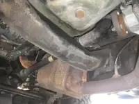
tranny ouput shaft to t-case input shaft alignment issue with vw 1.9TDI problem.

D2000

Well-known member
I have a VW 1.9TDI 1Z engine in my Samurai. I think the engine is deeper than the stock samurai engine. I noticed that the output shaft of the tranny is not parallel with the input shaft of the t-case so the intermediate driveshaft is not spinning at constant velocity. This is causing some vibration and wearing out u-joints.

Does anyone else have this issue?

 
Offset isn't going to cause an out of parallel issue, nor is fore/aft position of the engine/transmission.  To get out of parallel, your engine/trans would have to be sitting at an angle in the frame.  

A u-jointed driveshaft by it's very nature isn't going to spin at a constant velocity unless it's dead nuts straight, at which point you wouldn't need u-joints in there anyways.  Are you sure that the intermediate shaft didn't end up out of phase?  

Beyond that, I'd be taking a good hard look at your mounts to make sure one or more hasn't failed, allowing the engine/trans and/or t-case to shift position.  
 
Ok, so I just saw your other thread on this...are you saying that your "out of parallel" is actually that the trans output shaft is at a different _height_ than your transfer input shaft, so that there is an up/down angle on the intermediate shaft? 
 
urbex said:
Ok, so I just saw your other thread on this...are you saying that your "out of parallel" is actually that the trans output shaft is at a different _height_ than your transfer input shaft, so that there is an up/down angle on the intermediate shaft? 

No, I'm not worried about a slight difference in height. Driveshaft is in phase. It's that the output shaft of the tranny is at a different angle from the input on the t-case. From my understanding of driveshafts, the flanges/shafts/yokes need to be parallel (image below). My issue is even worse than the bottom driveshaft in the image below because the tranny output shaft points slightly upwards and the t-case input also points slighly upward. Everything is a bit messed up down there because the stronger Forever Engine Mounts cause the engine to sit 3/4" lower and I'm wondering if the aftermarket T-case cradle is affecting the input angle. I'm going to put in some spacers in the engine mounts to raise the engine back up. After I made a custom tranny rear mount and lowered the tranny position so that the output and input were parallel I got rid of the vibration and unbalanced sound but the gear shift stick is very low and I don't want the tranny dropped down. I'm hoping I can raise the engine to get the tranny and t-case lined up properly without my intercooler pipes hitting the hood. I suppose it will just take a lot of tweaking.
ujoint_driveshaft_angle_alignment by Daryl Suen, on Flickr

 
D2000 said:
From my understanding of driveshafts, the flanges/shafts/yokes need to be parallel (image below).

Not entirely true...all these graphics that insist the two ends MUST be parallel are just dead wrong.  The important thing is that the angles of the pinion and trans/transfer case output need to match.  Up, down, left, right..doesn't matter. 

However, and this is the big one, USUALLY, running them parallel is what is going to result in the easiest match within the packaging of an automotive chassis, and also often easier to figure out where to set these things. 

This all ties in to the nature of how the u-joints work, in that they're constantly running through acceleration and deceleration while rotating.  Having the angles match is how the cancellation works, and by having two different angles on the joints, they will no longer be able to cancel each other out.  

For further proof that having both the pinion and transfer case pointing up can work, look at the way Rover did their stuff in the 70s on the full time 4WD rigs.  Because the engine was tilted up, this meant that the front output on the transfer case was also tilted up.  In addition, the axle pinion was tilted up as well.  Then they assembled the driveshaft to be slightly out of phase, somewhere a bit less than 45* out.  This all worked out to be pretty effective in cancelling out the vibrations on that shaft.  It wasn't perfect, but did work out pretty well.  


rt 011.webp

rt 012.webp

330-fd02fd8157.webp

Realistically, though I've never tried it, I suspect that given the relatively short length of the intermediate shaft on our Samurais, as long as the angles are close to matching, vibrations will likely be minimal regardless of where it's set.  I've never even checked the angles on mine, despite numerous drivetrain changes, and it's never been an issue (at least not on the intermediate shaft anyways...getting that stupid short rear driveshaft set up on a centered diff 14 bolt was a heck of a lot of not fun though, lol)
 
What I mean
Not entirely true...all these graphics that insist the two ends MUST be parallel are just dead wrong. The important thing is that the angles of the pinion and trans/transfer case output need to match. Up, down, left, right..doesn't matter.

However, and this is the big one, USUALLY, running them parallel is what is going to result in the easiest match within the packaging of an automotive chassis, and also often easier to figure out where to set these things.

This all ties in to the nature of how the u-joints work, in that they're constantly running through acceleration and deceleration while rotating. Having the angles match is how the cancellation works, and by having two different angles on the joints, they will no longer be able to cancel each other out.

For further proof that having both the pinion and transfer case pointing up can work, look at the way Rover did their stuff in the 70s on the full time 4WD rigs. Because the engine was tilted up, this meant that the front output on the transfer case was also tilted up. In addition, the axle pinion was tilted up as well. Then they assembled the driveshaft to be slightly out of phase, somewhere a bit less than 45* out. This all worked out to be pretty effective in cancelling out the vibrations on that shaft. It wasn't perfect, but did work out pretty well.


View attachment 253335

View attachment 253337

View attachment 253333

Realistically, though I've never tried it, I suspect that given the relatively short length of the intermediate shaft on our Samurais, as long as the angles are close to matching, vibrations will likely be minimal regardless of where it's set. I've never even checked the angles on mine, despite numerous drivetrain changes, and it's never been an issue (at least not on the intermediate shaft anyways...getting that stupid short rear driveshaft set up on a centered diff 14 bolt was a heck of a lot of not fun though

Not entirely true...all these graphics that insist the two ends MUST be parallel are just dead wrong. The important thing is that the angles of the pinion and trans/transfer case output need to match. Up, down, left, right..doesn't matter.

However, and this is the big one, USUALLY, running them parallel is what is going to result in the easiest match within the packaging of an automotive chassis, and also often easier to figure out where to set these things.

This all ties in to the nature of how the u-joints work, in that they're constantly running through acceleration and deceleration while rotating. Having the angles match is how the cancellation works, and by having two different angles on the joints, they will no longer be able to cancel each other out.

For further proof that having both the pinion and transfer case pointing up can work, look at the way Rover did their stuff in the 70s on the full time 4WD rigs. Because the engine was tilted up, this meant that the front output on the transfer case was also tilted up. In addition, the axle pinion was tilted up as well. Then they assembled the driveshaft to be slightly out of phase, somewhere a bit less than 45* out. This all worked out to be pretty effective in cancelling out the vibrations on that shaft. It wasn't perfect, but did work out pretty well.


View attachment 253335

View attachment 253337

View attachment 253333

Realistically, though I've never tried it, I suspect that given the relatively short length of the intermediate shaft on our Samurais, as long as the angles are close to matching, vibrations will likely be minimal regardless of where it's set. I've never even checked the angles on mine, despite numerous drivetrain changes, and it's never been an issue (at least not on the intermediate shaft anyways...getting that stupid short rear driveshaft set up on a centered diff 14 bolt was a heck of a lot of not fun though, lol)
What I mean is that the tranny output shaft is not parallel with the t-case input shaft so the two u-joints are not cancelling out the acceleration/deceleration. I have a Trail Tough MKII transfer case cradle which tilts the t-case downward towards the rear diff. This matches my rear diff pinion angle so that is good but I'm worried about the alignment with the tranny output shaft. I could lower the rear tranny mount which would tilt the engine/tranny downwards to match the t-case (but would it starve the front input bearing of gear oil?), or I could tilt the t-case to match the tranny and then adjust the rear diff pinion angle but my rear propeller shaft angle might be getting too steep with a 4.5" lift. Or, is there better solution?
 

https://www.helpavetshine.us/help-a-vet-shine
Top Bottom